 Using this small yet powerful 4W transmitter Hams (licenced amateur radio operators) can transmit Morse code signals to long distances in 20-metre band. Morse code communication with European and neighbouring countries is possible. The transmitter (refer Fig. 1) comprises an oscillator, driver, and power amplifier. The oscillator is crystal-controlled. For this, an inexpensive and readily available crystal with fundamental frequency of 14.314 MHz is used with the horizontal dipole antenna oscillator. The oscillator delivers power of about 200 milliwatts. The next stage is a class-C driver that delivers power of nearly 1 watt. The final stage is a class-C power amplifier wired around transistor BD139, which delivers power of 4 to 5 watts.
After assembling the circuit, connect a 12V, 5W bulb across the antenna’s terminals. Apply regulated 12-15V DC to the circuit. Adjust gang condenser’s knob until the bulb glows, which indicates that the
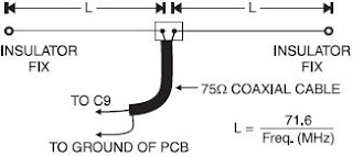
transmitter is okay. (Caution. Don’t switch on the transmitter without an output load.) After checking with bulb as load, the transmitter can be connected to a horizontal dipole antenna via 75-ohm coaxial cable as shown in Fig. 2. Each arm of the dipole antenna is about 5 metre long. The correct length L (in metres) of single pole of the antenna can be calculated using the following relationship: L = 71.6/ frequency (MHz) Winding details of coils are as follows: L1: 9 turns of 24 SWG insulated copper wire over 8mm dia. oscillator coil former with ferrite bead L2: 3 turns of 24 SWG insulated copper wire over coil L1 L3: 9 turns of 24 SWG insulated copper wire over 8mm dia. former with movable ferrite bead L4: 14 turns of 20 SWG insulated copper wire over 1.5cm dia. PVC former. (The coil is to be tapped from 9th to 10th turn from the top end.) RFC: 12 turns of 36 SWG insulated copper wire using TV balun core Warning. Use of this transmitter without Ham licence is illegal, hence only Ham licence holders should assemble this project.


No comments:
Post a Comment